
| INSTALL | BOOSTER ECU: VOLVO SPA T5/T6 Engines

The following guidelines are instructions for installation of the VAITRIX Booster ECU for all VOLVO SPA Engine vehicles (T5 and T6).
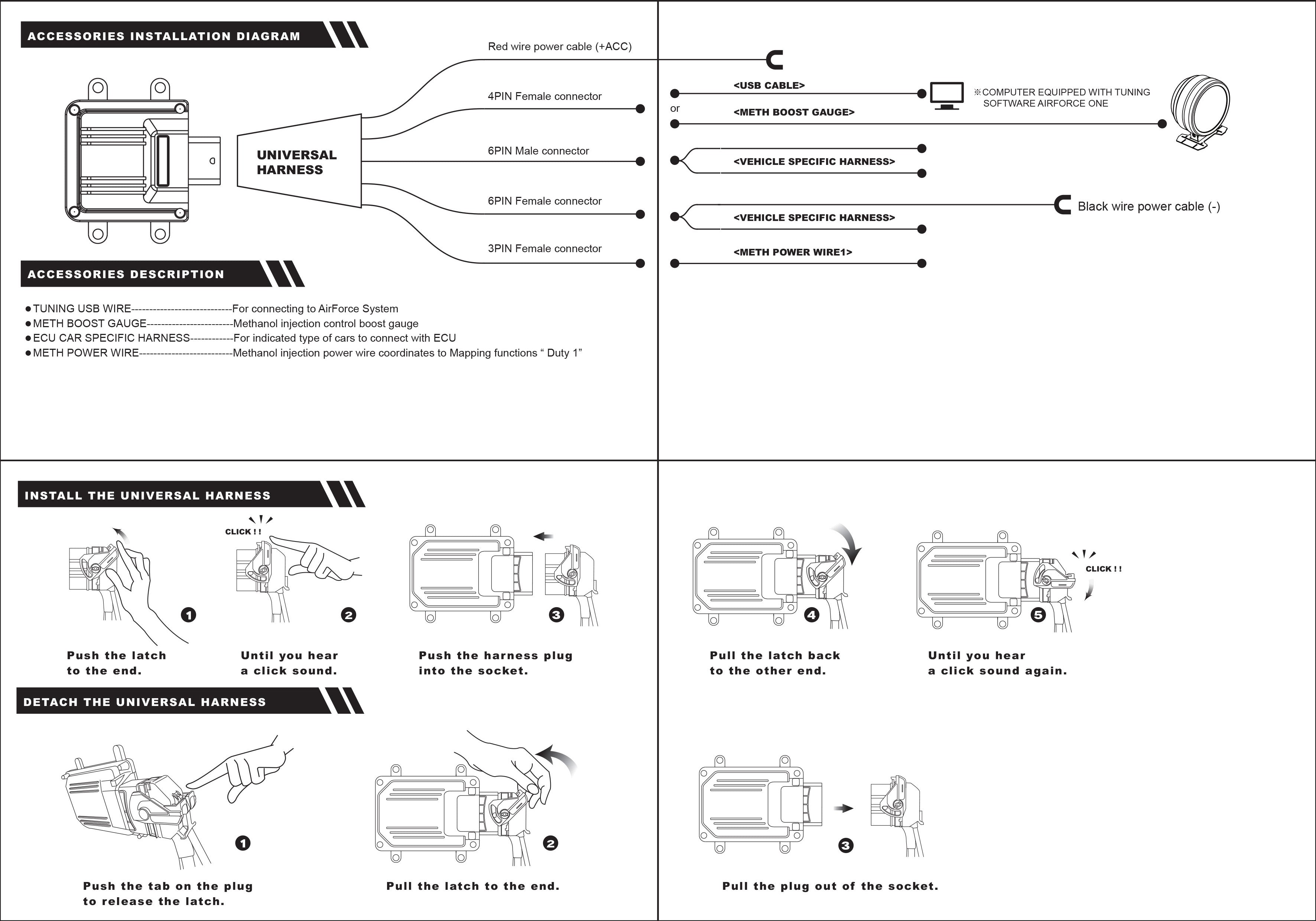
PARTS FOR INSTALLATION:
- - Vaitrix Booster ECU Unit with Universal Harness (Basic or Pro)
- - Vehicle Specific Harness
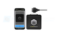
- - Bluetooth Module Cable
- - Add a Fuse
- - Two sided wire connector (red)
- - 3M sticky pads for mounting


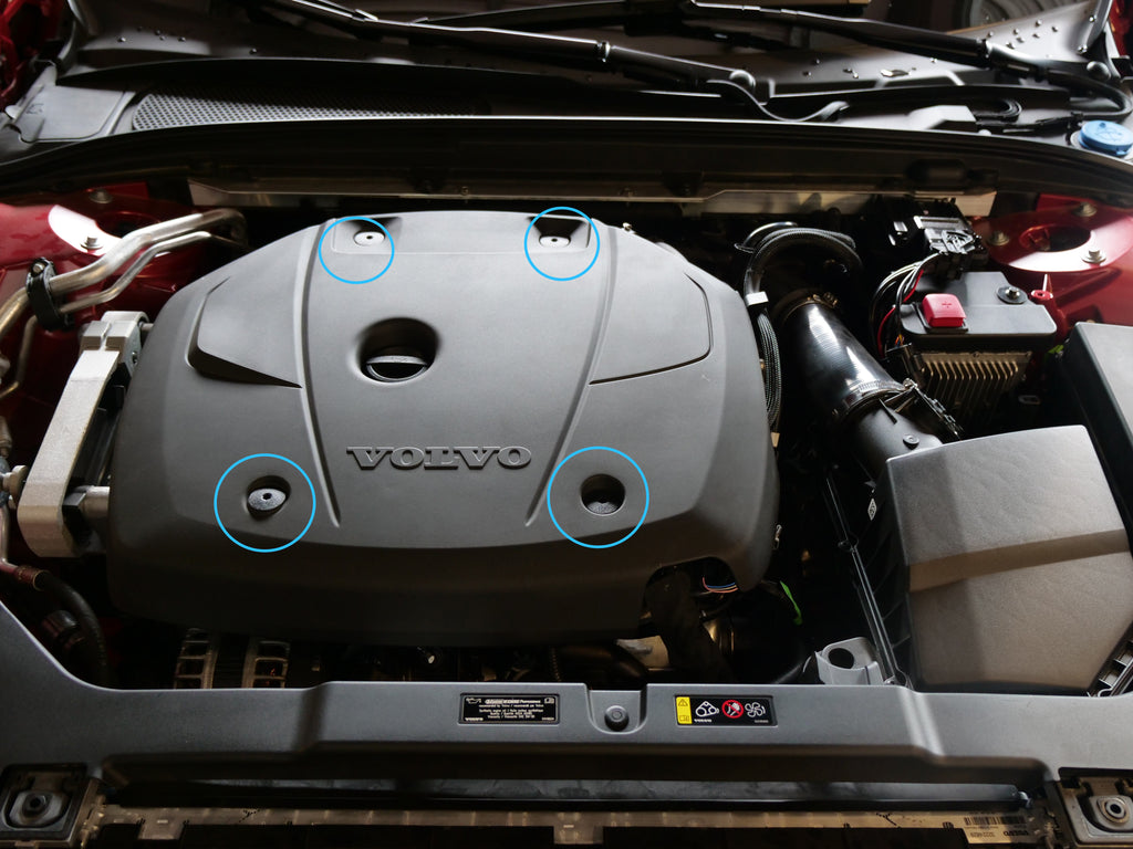
1. Remove the engine cover. Use a Torx fitting to loosen the fasteners (they do not pull out completely), then simply pull the engine cover off of the engine.
2. Disconnect the negative battery terminal before working with sensors, located in the trunk compartment.

3. Connect the vehicle specific harness to the (3) sensors shown below:
-A. Camshaft Position
-B. Manifold Sensor
-C. Boost Sensor (located on the intercooler piping).
Each connector is different, so it is very difficult to get the wrong connectors on the wrong sensor. You will connect the factory harness into the Vaitrix female connector, and connect the male connector to the factory sensor.

4. Connect the vehicle specific harness connections to the universal harness, which will lead back to the Booster ECU. Again, this connections only fit one way and are all different, so it's difficult to get them mixed up.

5. You can now mount your Booster ECU inside the engine bay. You can mount the unit anywhere or according to your preference. We have chosen to mount it on top of the AUX battery unit in the engine bay.

6. Connect the bluetooth module cable to the universal harness. It has (2) connectors: a communication connection and a power connection. You can then route the bluetooth module anywhere in the engine bay. For best signal,we recommend the space to the side of the fuse box on the driver side of the engine bay.


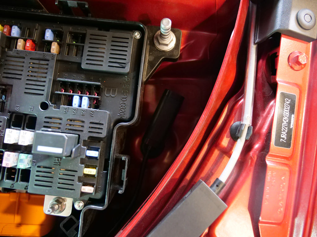
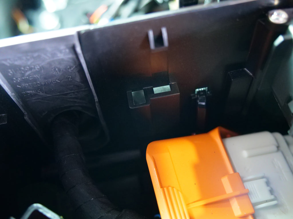
7. Now you will route power to the Booster ECU. Use the red power wire coming from the Universal harness, and cut off the ring connector at the end (not too much). Run this wire through a hole in the side of the fuse box near the intake filter box. We will be using an empty fuse slot inside to power the booster at ignition on.
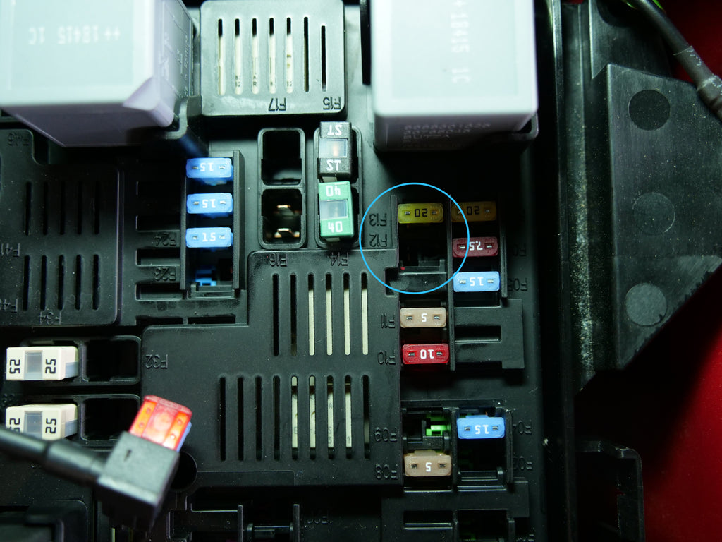
8. Now take the add a fuse provided in the kit, and plug the add a fuse into the F12 slot on the fuse/relay panel.
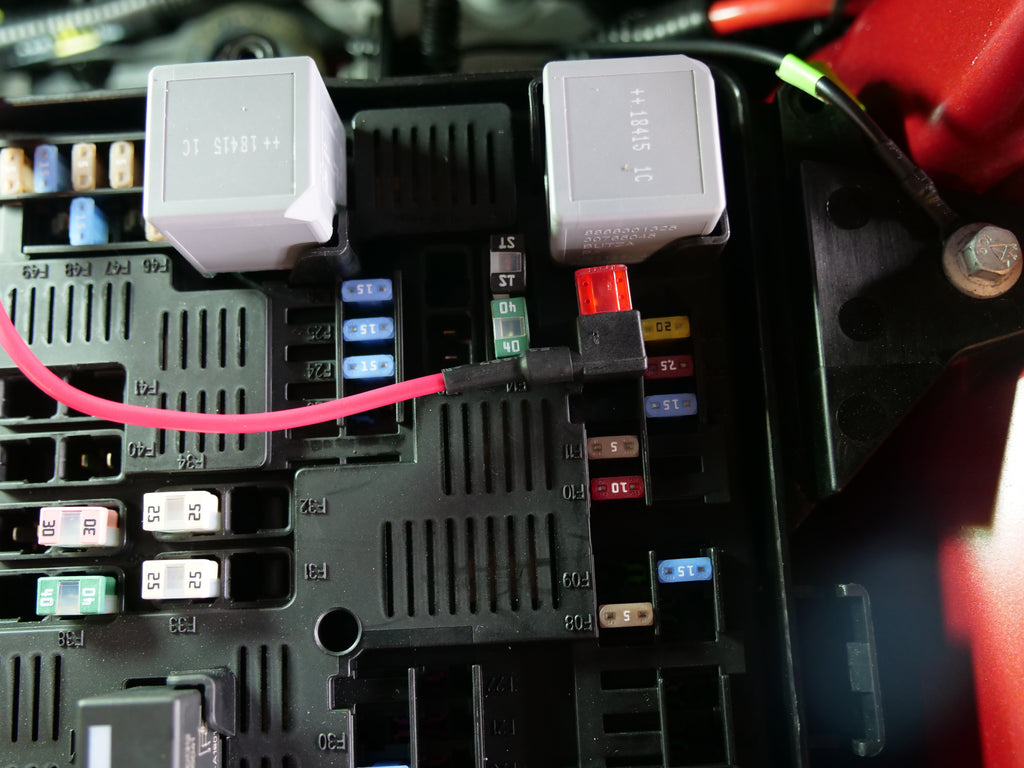
9. Now join the Booster power wire and the add a fuse wire together using the two sided wire connector (red) provided in the kit.

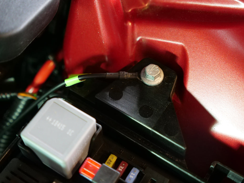
10. Connect the ground wire (attached to the vehicle specific harness section that connects to the camshaft position sensor), and connect it to the bolt located above the fuse box panel (mounting position for the fuse box).
FINAL STEPS:
Button up the engine bay (fuse box cover, engine cover, any other area you were working in), and use the provided zip ties to consolidate wiring together. You can also route your wires which ever way you feel comfortable with. Our test car has the wiring routed underneath the intake area so that it stays out of sight.
Reconnect the battery, and proceed to turn the ignition on. Make sure there are no pending check engine lights or error messages. If you receive one, a connection is not secure or tight on the harness.
Once all is clear, you can start the engine. Average time for vehicle adaptation is 80-150 miles.
In order to put the car back to stock, you can use the Vaitrix AIR FORCE GO mobile app via bluetooth, and set the Booster back to stock settings. You can also disconnect the fuse relay located on the Booster ECU power wire outside the fuse box. This can be removed, and the Booster will allow signal to pass through, putting the car back to stock without you having to remove the harness or unit.
If you have any questions or concerns, please contact support@vaitrixusa.com.