


UPGRADED SECONDARY HEAT EXCHANGER SYSTEM (ALFA ROMEO GIULIA 2.0L)
Introducing the EUROCOMPULSION UPGRADED SECONDARY HEAT EXCHANGER system for the ALFA ROMEO GIULIA 2.0L.
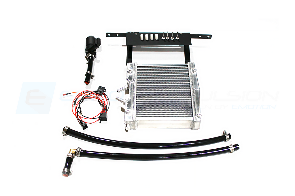
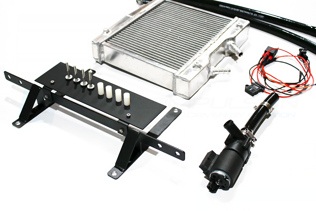
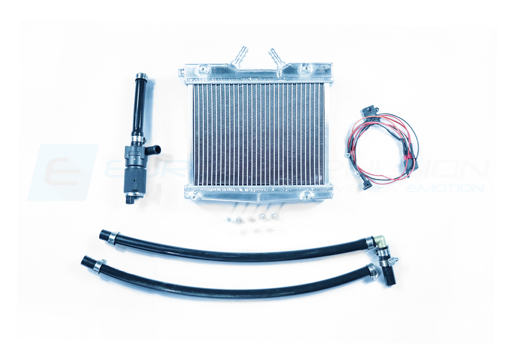
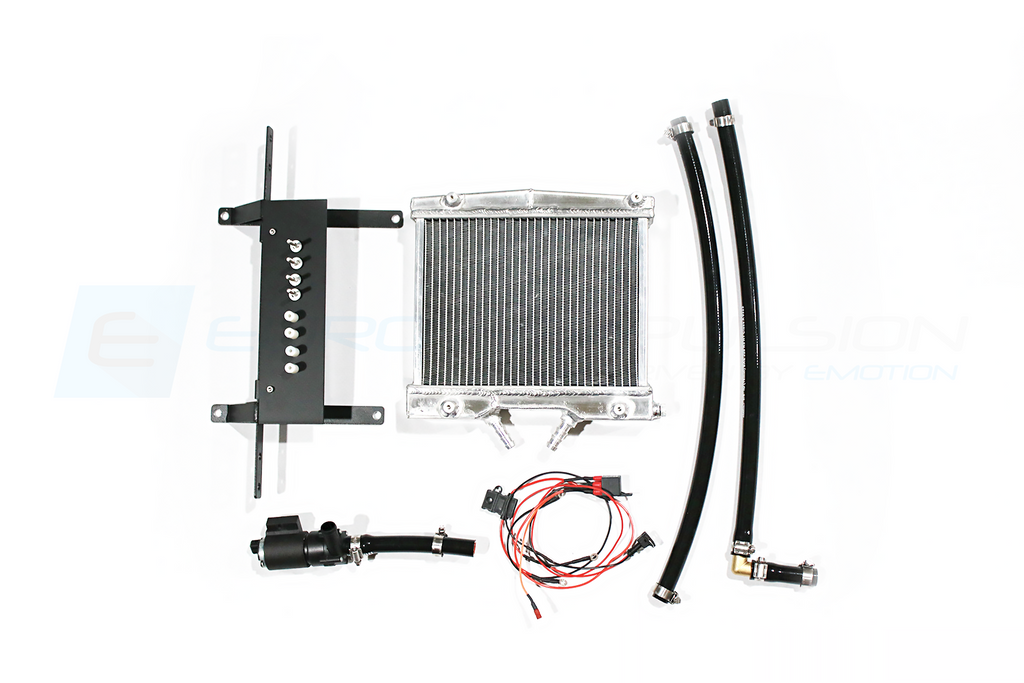
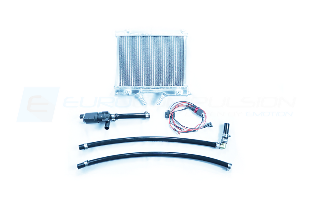
Lower your intercooler temps to support more consistent and reliable POWER! This heat exchanger upgrade is an add on system to the existing factory heat exchanger and plumbing in the Giulia 2.0L. This kit comes with everything needed to integrate smoothly into your factory setup, including it's own mounting system, bracket, hose supply/fittings, and it's very own supplemental coolant pump with wiring harness.
The Giulia 2.0L's liquid to air intercooling system has two purposes:
- Primary intercooling system, cools hot charge air coming from the turbo to keep intake air temperatures in check.
-
Cooling the turbo itself.
The system has only just enough capacity to handle both of these tasks on a stock car in normal usage. Alfa Romeo knows this, which is why they added an additional heat exchanger to the system in the heavier Stelvio powered by the same engine.
On a modified car, especially one that will serve track duty, increasing the capacity of the Giulia's system as the factory did on the Stelvio is a good idea and that's exactly what the Eurocompulsion Secondary Heat Exchanger Upgrade does.
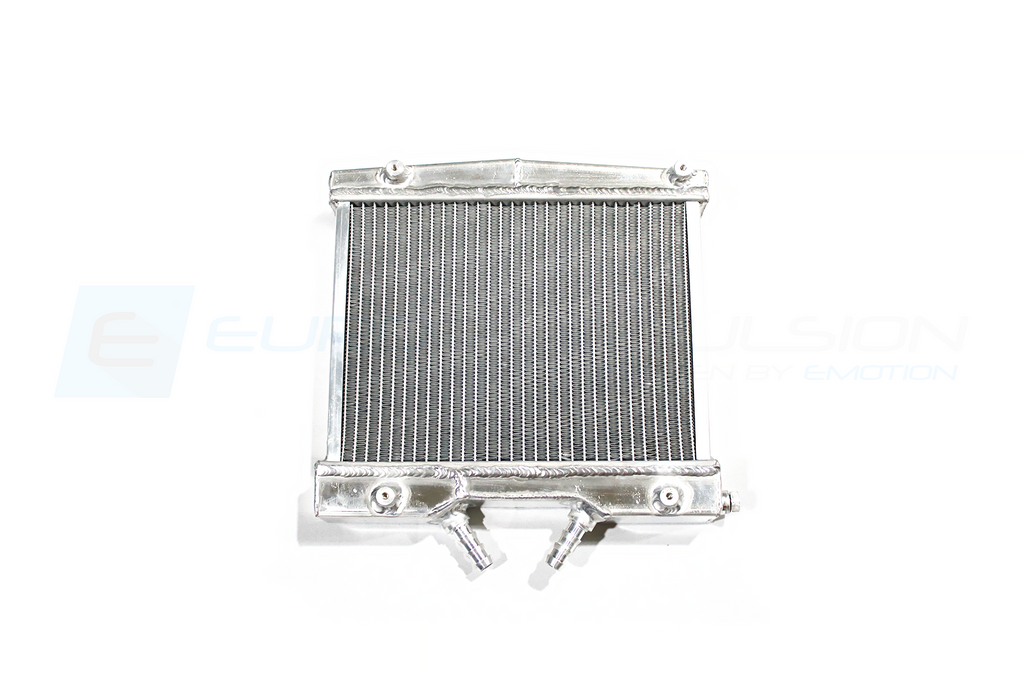
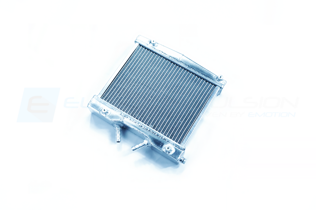
However, we went beyond the factory solution. Our heat exchanger is TWICE the size of the factory's additional unit in the Stelvio and QVs, and we utilize an additional pump to assist with circulation, making cooling more effective. This gives the car more intercooling and turbo cooling capacity than even the factory Giulia QV! This enhances performance, reliability, and is a very worthwhile upgrade.
In addition to size, it's all about location, location, location. Our upgraded secondary unit sits front and center in the V Grille, where the largest source of ram air at the front bumper is seen (rather than situated off to the side in the bumper cheek). This allows our unit access to the largest amount of airflow to assist in cooling the intercooler coolant within. During our initial air intake development, we tested different areas of the bumper at the front of the car while driving with a manometer to determine the highest pressure areas for ram air. The area in the Grill "V" was more exposed to higher amounts of ram air pressure than the bumper cheek.
This secondary heat exchanger has been used on our own daily driven Giulia (w/ our Big Turbo Upgrade) with 400+ PROVEN horsepower at the track, drag strip, and street. This upgrade will handle whatever you can throw at it.
WHY NOT JUST USE THE STELVIO 2.0L, QV, or EVEN THE MASERATI GRECALE FACTORY SECONDARY UNIT SETUP?
In a nutshell, our secondary unit and setup is superior. It is larger, has more cooling volume, easier to install, more efficient, inexpensive, and more effective in increasing/maintaining performance.
-
The factory system components needed to copy the Stelvio 2.0L and QVs would be cost prohibitive (aka more expensive than it needs to be), and require you to make exterior changes to the car
- Loss of Brake Cooling ducts
- Not plug and play
- EC unit is larger/has more cooling volume (130% increase) (246ci vs 107ci)
- EC unit has supplemental pump to support the existing factory pump
- EC unit is plug & play
- EC unit has superior location in the bumper
- Why pay more and do more work to source inferior OEM parts when you can fabricate the correct parts to do the job right
FEATURES:
- Independent system, Integrates with the existing factory cooling system
- Completely plug and play
- Weight of system: 5.8 lbs
- 130% Larger Core Volume compared to OEM secondary units (in Stelvio 2.0L & QVs) (246ci vs 107ci)
- Expanded End Tanks, Improved Heat Dissipation
- Lower Intercooler Temperatures (Reduced Manifold temps by up to 20F)
- Lower Intercooler Coolant Temperatures (Reduced IC coolant temps up to 16F)
- Improved performance & power consistency in all driving conditions, including at Part Throttle and Wide Open Throttle (WOT)
- Thoroughly tested in all seasons and on the track, drag strip, and street
- Great for Stock, Tuned, or Heavily Modified Giulia 2.0Ls (like our Big Turbo Giulia)
- Includes all necessary hardware, hoses, and wiring to mount and install
IMPORTANT PRODUCT NOTES:
- 1-2 Gallons of Additional Factory Coolant will be needed for installation.
- Requires Eurocompulsion V2 or V4 Intake
- Will not work on some EU crashbars
INSTALLATION INSTRUCTIONS:
- ALFA ROMEO GIULIA 2.0L (INSTALLATION)
- or SEE INSTALLATION TAB (ABOVE)
TECHNICAL / TESTING INFORMATION (SEE TECH INFO TAB ABOVE):

APPLICATIONS:
- (ALL) ALFA ROMEO GIULIA 2.0L (WORLDWIDE: NA, EU, AUS ASIA)
HOW THE FACTORY INTERCOOLING SYSTEM WORKS
The factory intercooler system (known as the LT Cooling System) uses the main radiator for the LT system and the additional radiator (R2) for the LT system. at the front of the car and in the cheek/bumper to cool the coolant running to the intercooler system, which is a liquid to air intercooler. This intercooler takes in charge air from the turbo, and uses the internal coolant to cool the charge air before entering into the manifold/engine.
The Giulia 2.0L does not come from the factory with this additional radiator (R2) for the LT system).
Our upgraded secondary heat exchanger system adds a secondary unit where there was none before on the Giulia 2.0L (serving as the R2 radiator from the diagram, but in a new and more optimized location at the front of the car).
The EC "SHE" system for the Giulia 2.0L more than doubles the available core volume of the additional heat exchanger in the Stelvio or QVs, thus increasing the cooling capabilities on the circulating coolant. This coolant is then delivered to the intercooler system colder than it was before. This is also supported by a supplemental pump, designed to assist in circulating coolant through the additional exchanger more efficiently, resulting in more rapid and effective cooling.
This contributes greatly to the capability of the intercooler to more effectively cool the charge air, resulting in lower temperatures (and better power, while supporting more tuning changes).
Pictured below: Alfa Romeo Stelvio 2.0L

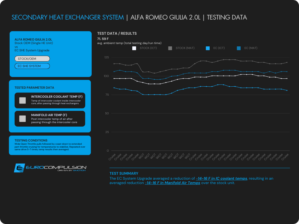
The EC Secondary Heat Exchanger was tested against the single STOCK OEM unit. This Giulia was driven at cruising speed/part throttle, then going WOT (wide open throttle), through various gears, letting off at redline and resuming cruising speed/part throttle to allow temperatures to stabilize. Then repeat.
This was done 5-7 times per drive, with an average ambient temperature that day of about 71-72 F. Average temperatures were calculated and graphed.
The following is an installation guide for our EC Secondary Heat Exchanger System for the Alfa Romeo Giulia 2.0L. This project is relatively involved and can take up to 3-4 hours to complete. Take your time to prevent mistakes and any damage to the fins of the new heat-exchanger.
*You will need about 1-2 Gallons of OEM Coolant to refill the coolant drained in the beginning, as well as accommodate the larger core size of this heat exchanger and lines.*
Start by removing the lower body shield. Once removed remove the remaining bolts under the bumper. Here is a picture showing all the lower bumper screws.


Once the lower bumper screws are out we will move to the fender wells and remove the screws pictured below. Note: There will be a lower screw holding the fender lining to the bumper cover. There are also 10mm bolts on either side where the bumper meets the fender(inside the liner).

Next we move to the 6 top bolts + 2 push pins holding the bumper. The hood will need to be open to access these. Illustrated below. Note: you will need to lift the bumper to free it from the center holes on top. Be ready to disconnect any electrical wire between the bumper and body!

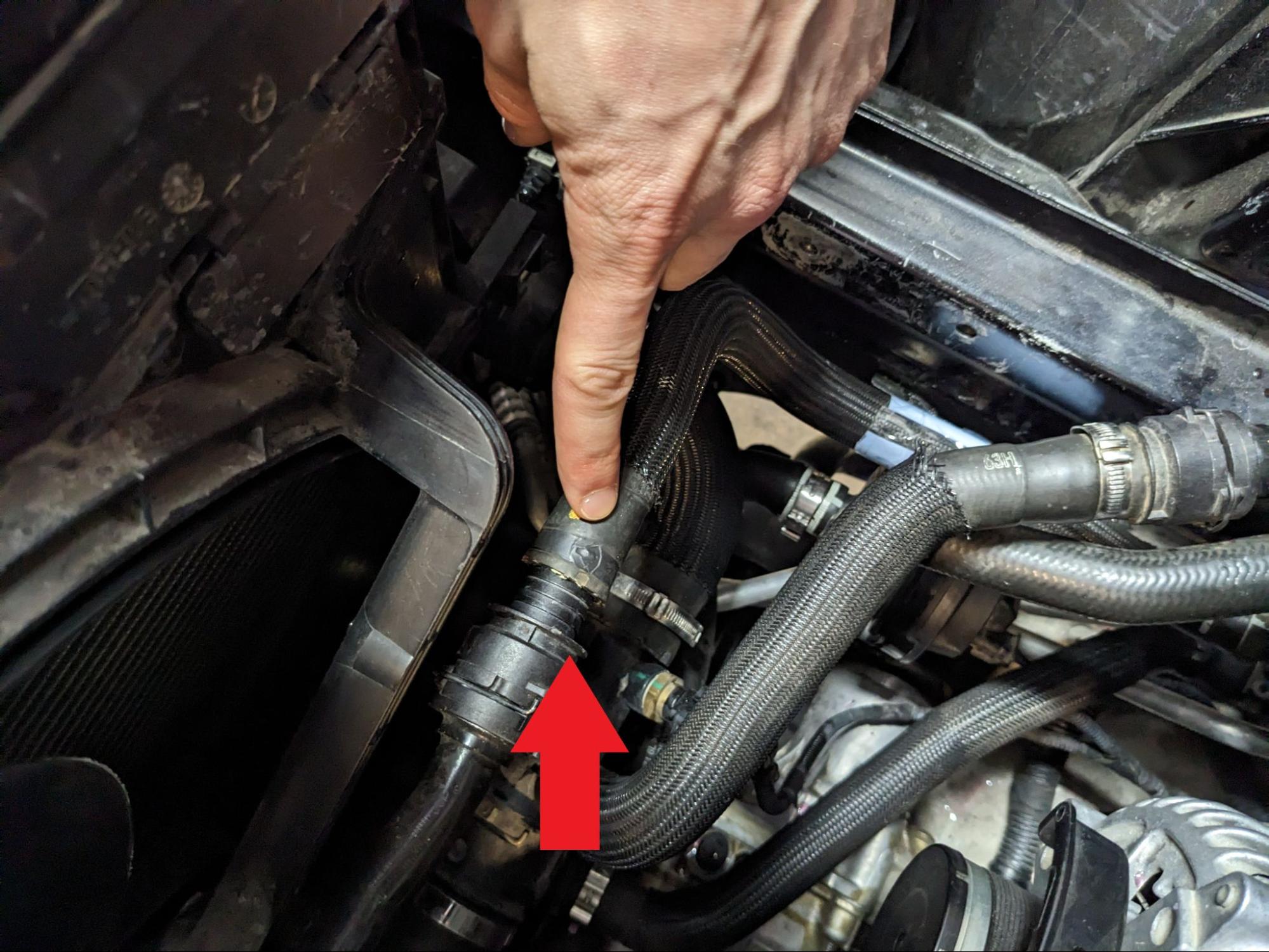
Once the bumper cover is completely removed we will start to drain the coolant system by loosening the plug on the driver side of the radiator. There will still be some remaining coolant in the large coolant line we are about to remove so have some pans ready in case of spills. This will get messy. To access this hose the air intake box will need to be removed (V4 canister or V2 Bracket + Filter). The factory coolant hose lays below the intake box. You will need to remove the clamp on either side and pry until free from the fittings.

FRONT OF CAR
PASSENGER SIDE

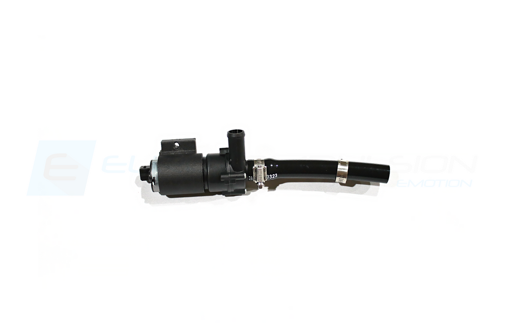
Once the hose is removed you will see where we will be mounting the bracket and the new pump. Use the included hardware to mount the pump.

Below I will show what the pump should look like with both the V4 bracket and V2 bracket.
The pump will be located and mounted in front of the lower portion of either intake bracket.
V4 PICTURED

V2 PICTURED

Once the pump is in place we will start running our coolant lines. First line to do is the line between the new pump and check valve. Use a lot of soapy water on the fittings and inside of hose to help slide over the pump and check valve. Use the provided clamps but do not tighten them yet.
Note: This hose will be labeled as A.

Next you will need to locate the inside passenger side radiator shroud to create some access holes for the new hoses you are about to run. We used a step drill bit and drilled the holes out to 1 inch in diameter.
Note: We show the placement of the holes below. We found this to be the best spot for a pass through. Don't be intimidated by this part, you may be drilling but this is quick and simple!


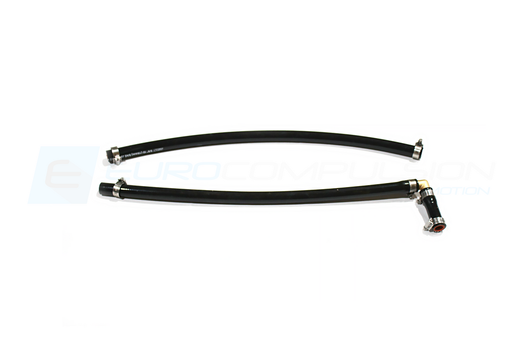
Once the pass through holes are drilled we will start running our first silicone radiator hose.
Picture below is the factory fitting we will be connecting to. Use the included clamp to secure this hose. It will be run between the frame rail and the ac lines to the front of the car to the pass through holes.
Note: This hose will be labeled as B. This will connect to the bottom of fitting of the heat exchanger

The next line will run from the new pump to the upper fitting on the heat exchanger. This hose has a 90 degree fitting on one end.
Note: Hose will be labeled as C.

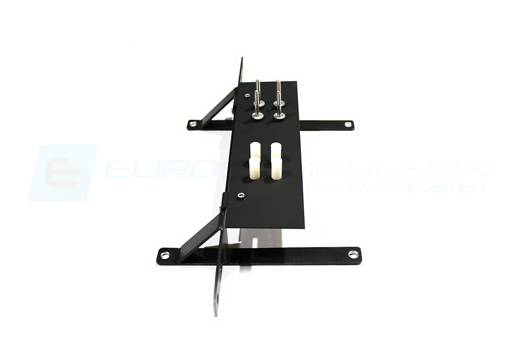
Once both hoses are passed through the radiator shroud we will start on the heat exchanger itself. First remove the four bolts holding on the two black angled pieces of steel. Shown below. These bolts will be reused to mount the heat exchanger bracket.


Next, we will mount the heat exchanger bracket using the 4 bolts and angled pieces of steel you removed previously in the above steps.


Next we will mount the heat exchanger to the bracket using the 4 included bolts, nylon spacers, and washers. Secure the top bolts first and leave them loose to allow all four bolts to be threaded in.
DO NOT FORCE THE BOLTS. This is very easy to cross thread. Once the heat exchanger is mounted you can push the hose onto the fittings. And secure with clamps.

Note the clamp orientation for easy access to the clamps.

Once the heat exchanger is secured and the hoses are fully secured with clamps tightened at both ends we can start to move onto the bumper. You will need to remove the trim piece directly behind the V grill on the bumper. It is held by two hex head bolts.


Removing this piece allows for the installation in the next step.
Not shown is the vanity plate which will bolt to the heat exchanger bracket to cover the exposed crash bar. It will cover the portion of the crash bar where you see black tape and our "E" logo in the pictures above. This piece is not of structural importance to the kit, but will help with aesthetics of the front grill.
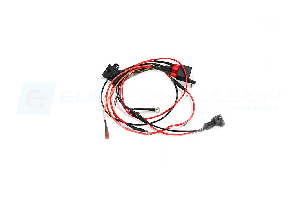
Next we will move onto the wiring portion of the kit. This kit is plug and play but does require a mounting of a relay and sourcing the main power.
Below we will show how the relay is mounted and how the wires are routed. You can power this pump with your own method but we think it being on a relay that is fused protected is the best setup.
First locate the stud coming out of the shock tower. This is where we will mount our relay and both of our ground points.

The relay, relay ground, and pump ground will use this stud.
Next locate the ignition power wire from the harness plug nearby (close to the ECU).
Shown below, you will need to connect to the ORANGE WIRE with BLACK STRIPE in this harness.

The main red wire off the relay will be our main power source and that is located in the cowl fuse box area.

Here is a photo showing what each wire on the relay will go to.

Once the pump is wired in we can start by closing the radiator valve we used for draining the lines earlier.
You will need to fill the system and have the cap to the tank remain off as it purges potential bubbles in the lines. This will take more coolant than drained because of the new larger capacity of the heat exchanger and added lines.
You can start the car during this process to monitor for any kind of leaks. Once the coolant is full you can reassemble the bumper and intake system.